
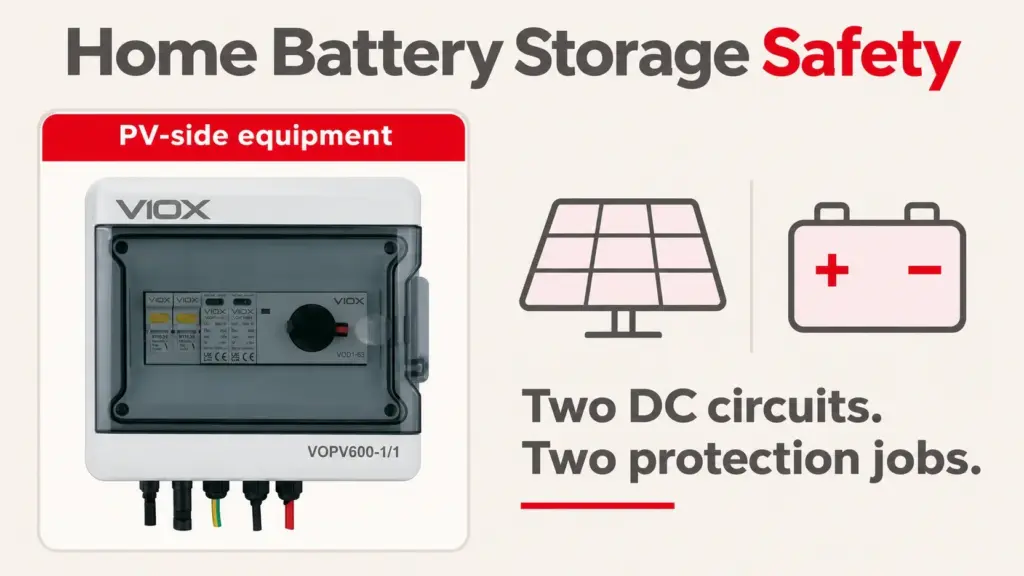
Short Answer
Yes, a properly selected, installed and maintained home battery system can be used safely, but it is not risk-free. Check the PV-array DC circuit and the battery DC circuit separately: each needs suitable connections, cables, isolation and overcurrent protection. LFP generally offers better thermal stability than NMC, but chemistry does not replace installation quality or a working battery management system. Available rooftop-PV fire findings do not establish that most home-battery fires start in wiring rather than cells.
The useful handover question is not just "Which battery chemistry did I buy?" It is "What protects each DC source, and where is that protection documented?" A good battery cannot correct a poor termination, and a well-built PV combiner does not establish that the battery feeder is protected.
Published research, including RWTH Aachen's assessment of home-storage fire likelihood, reports low observed fire likelihood in the populations studied. That is reassuring context, not a guarantee for every product or a global cause-of-fire ranking. This checklist focuses on practical installation evidence rather than an unsupported universal percentage.
What actually causes home storage fires
These are possible failure pathways, not a statistical ranking. They can interact: a wiring fault can heat nearby equipment, while a battery fault can expose its feeder to substantial current.
DC wiring and connections
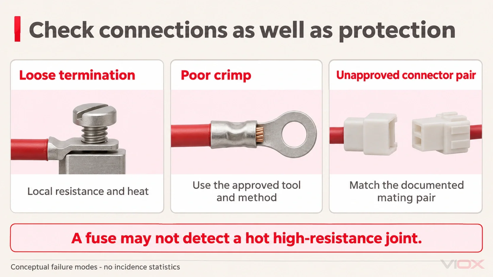
Loose terminals, poor crimps, unsuitable cable sizes and unapproved connector pairs can produce local heat, insulation damage and arcing. A high-resistance connection can overheat while the overall circuit current remains below a fuse or breaker's trip threshold. Overcurrent protection therefore does not remove the need for correct connections.
TNO's investigation of Dutch PV fire incidents identified faulty connector connections as a recurring concern and discussed cross-mating between connector brands. That evidence concerns PV installations, not the relative causes of residential battery fires. It supports checking the PV wiring; it does not justify blaming most storage fires on connectors or excluding battery faults.
For PV joints, use the documented mating pair, contact, cable and assembly method. "Fits together" and "compatible with" are not sufficient evidence. Staubli's cross-connection guidance explains why mixing connector brands can create uncontrolled interface risks.
Missing or incorrectly selected DC overcurrent protection
A short circuit can remain uncleared if the required protective device is absent, bypassed or unsuitable for the circuit. Selection includes DC voltage, current/time behaviour and the ability to interrupt the prospective fault current, not just the ampere value printed on the front.
An undersized fuse is a different problem: it may operate unnecessarily and tempt someone to fit an unapproved larger spare or bypass it. The remedy is a coordinated design, not simply "more amperes." Nor should a fuse be assumed to clear every series arc or heating joint. The Ontario solar-PV firefighter guidance specifically notes that arcing fault current may be too low for protective devices to operate.
Battery-side control and assembly faults
An incompatible charging profile, faulty charger control or a failed battery management system (BMS) can allow operation outside the battery's limits. The BMS must do more than display a state-of-charge number: the approved system needs a defined response that stops charging or discharging when required.
An improvised pack of unmatched, untraceable or counterfeit cells adds uncertainty about cell behaviour, balancing and protection. A label claiming a particular chemistry does not verify the complete pack. The UK government's Domestic battery energy storage systems review addresses battery failure mechanisms and the design and installation measures needed to reduce their risk.
Cell faults and thermal runaway
Internal cell defects, damage and electrical or thermal abuse can initiate thermal runaway. Cell-related hazards remain real even when the external wiring is correct; installation checks should not erase them from the risk assessment.
LFP is generally more thermally stable than NMC, as explained in the UK government's energy-storage safety guidance. This is a chemistry comparison, not a residential fire-rate estimate. There is no single universal runaway temperature that proves all LFP products safe, and LFP systems still need appropriate design, BMS control, placement and protection.
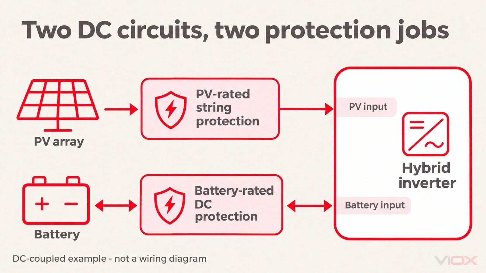
Two DC circuits, two protection jobs
A DC-coupled solar-and-storage installation connects the PV array and battery to separate inverter inputs. AC-coupled storage uses a different arrangement, but its battery circuit still needs its own documented protection. Do not treat a shared inverter enclosure as evidence that the DC source circuits are interchangeable.
| Circuit | What flows | What protects it | What can go wrong when protection or connections are unsuitable |
|---|---|---|---|
| PV array DC: strings to the combiner/protection point and inverter | Solar-generated DC; parallel sources may feed reverse current into a faulted string | Coordinated gPV string fuses where required, suitable DC isolation, PV-rated surge protection and the specified conductors/connectors | Damaging backfeed, an uncleared fault, overheated joints or inadequate isolation; a surge protector does not replace a fuse |
| Battery DC: battery system to its inverter/charger | Bidirectional charge/discharge current, with battery fault-current capability that must be assessed separately | Battery-system BMS and controls, documented battery-circuit fuse/breaker protection, suitable DC disconnection and approved cables/terminations | Uncleared battery-fed fault current, cable damage, sustained heating or failure to stop charging; a BMS label alone does not prove cable short-circuit protection |
The battery's current rating and prospective short-circuit current are separate quantities. A protective device must carry the intended duty and safely interrupt the available fault, within its declared DC conditions. Victron's Wiring Unlimited DC-wiring chapter explains why fuse interrupt ratings matter for lithium battery circuits.
The PV-side checklist
- Confirm string protection need and the fitted links. Where individual string protection is required, identify each protected string, the gPV link and the approved polarity arrangement. A single-string or independently routed MPPT design may not need an external fused combiner merely because a battery is present.
- Document DC isolation. Ask what the switch disconnects and what remains energized. Opening a DC isolator or switching off the inverter does not make illuminated modules or all incoming array cables dead.
- Check the PV surge-protection scope. Where a Type 2 DC SPD is specified, confirm the exact voltage/application match and the installed arrangement; its surge rating is not battery fault-current protection.
- Use matched connector interfaces. The default is the same manufacturer and documented mating family/type on both halves, with the specified contacts, cable and tooling. Resolve any claimed cross-brand equivalence with explicit approval evidence; do not unplug PV connectors under load.
- Obtain the termination record. Qualified personnel should use the maker's torque value, tool and method. Record who checks the work and how any later recheck is performed. Do not loosen or routinely retighten connections unless the manufacturer specifies that method.
- Agree the inspection plan. Include a qualified thermal review after the first operating season if appropriate to the system, and follow the equipment maker's service schedule. Compare findings under meaningful operating conditions rather than relying on an isolated temperature image.
Series blocking diodes are a separate design question; see Do Solar Strings Need Blocking Diodes?.
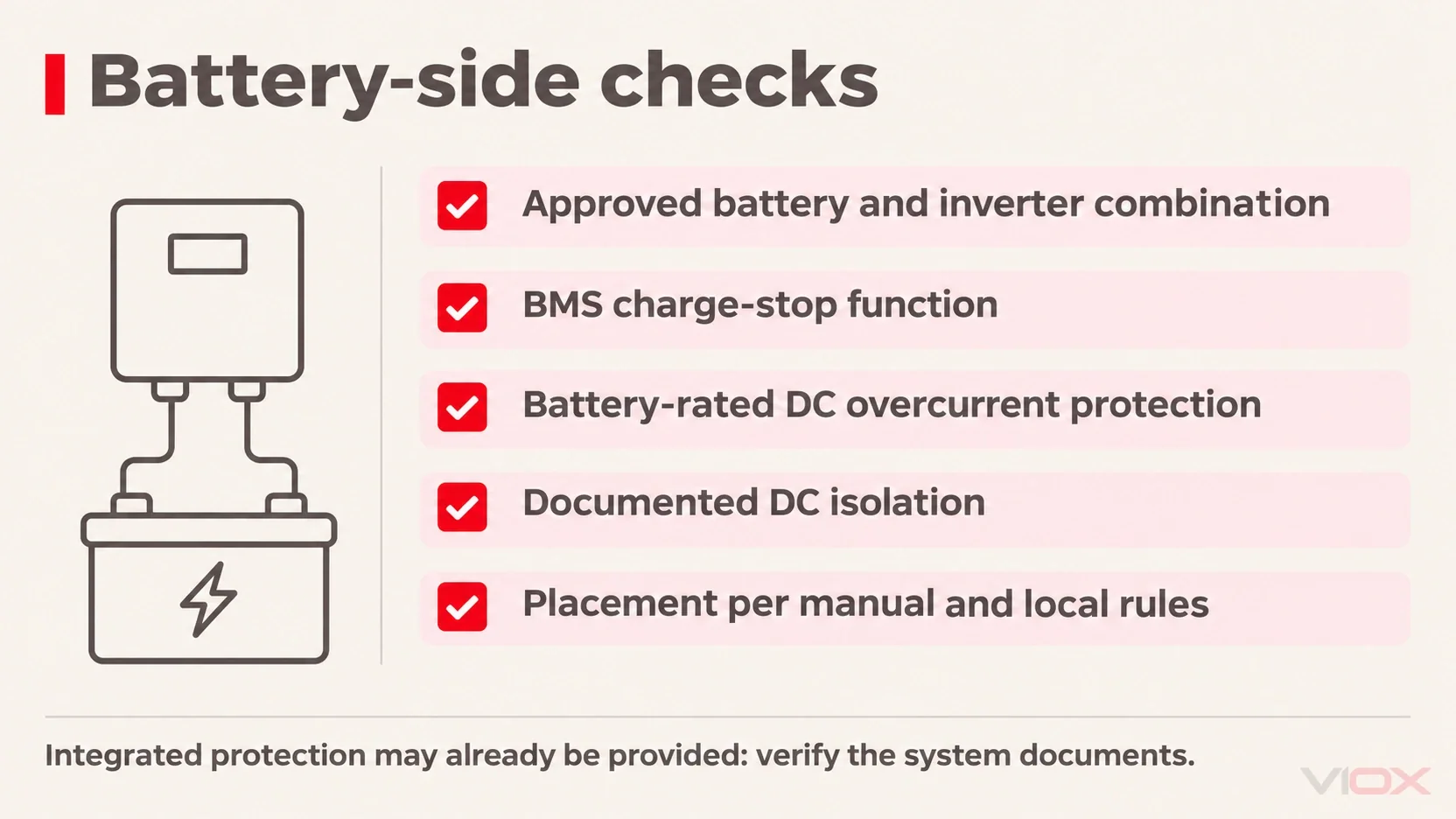
The battery-side checklist
- Buy a documented system combination. Check the battery and inverter/charger pairing, applicable market certification or approval evidence, installation manual, warranty and recall status. A compliant component alone does not establish approval of an improvised complete system.
- Verify the BMS response. Ask how cell voltage and temperature limits stop charging/discharging, what device or command executes that response, and how communication failures are handled. A monitoring screen is not proof that the protective response works. Victron's BMS design guide illustrates this distinction between monitoring and control; use the installed battery's own instructions.
- Identify battery-circuit overcurrent protection. The approved design must specify the fuse/breaker arrangement, its DC duty and interruption capability, and its position at or close to the battery source as required by the manual and local rules. Protection may already be integrated in a certified assembly. Ask how the cable segment before any external protective device is protected; do not assume a PV string fuse is a battery fuse.
- Identify DC disconnection. Have the installer label the intended isolation point and explain the normal shutdown procedure, access and operating limits. Homeowner access means an approved operating control, not opening a battery enclosure or exposing live terminals.
- Check placement, ventilation and access. Follow the exact battery manual and local requirements for clearances, environmental limits, ventilation, escape routes and fire precautions. Do not copy a generic distance or improvise ventilation openings in a sealed unit.
If the battery shows smoke, swelling, unusual heat or repeated safety alarms, follow its emergency instructions, move people away and contact emergency services when appropriate. Do not approach a smoking unit to operate a switch or remove covers. Arrange qualified assessment before reuse.
Five questions to ask your installer
- Who records terminal torque and performs any manufacturer-specified recheck?
- Which PV strings require fuses, and where is each fitted link documented?
- Are all connector joints the approved matched brand/type and cable configuration?
- What battery-circuit DC protection is fitted, where is it, and what fault-duty evidence supports it?
- What exactly does the BMS do on overcharge, and how does it stop the charging source?
Where VIOX Solar products fit
The VIOX product fit in this guide is the PV-array DC side. Vioxsolar does not sell batteries, battery fuses or battery disconnects; the battery checklist above is general buyer guidance, not a recommendation of those products from VIOX.
The verified VOPV600-1/1 and VOPV1000-3/1 pages document 600 V and 1000 V combiner/protection models, within the published one-to-three-input range. Their listed assemblies include VOPV-32 holders with 15 A, 10x38 mm string fuse links, Type 2 40 kA DC SPDs, VOD1 isolation and IP65 enclosures. Confirm the exact circuit arrangement and that the supplied links suit the modules.
The VOPV-32 platform lists 10x38 mm links, 1-32 A options, 1000 V DC and a stated 33 kA platform breaking capacity. The separate VOPV-63 platform lists 14x51 mm links, 8-50 A options, 1000 V DC and 50 kA. These are published platform data for the exact documented link-holder combination, not stand-alone interruption ratings of empty holders. The cited combiner BOMs do not establish VOPV-63 installation.
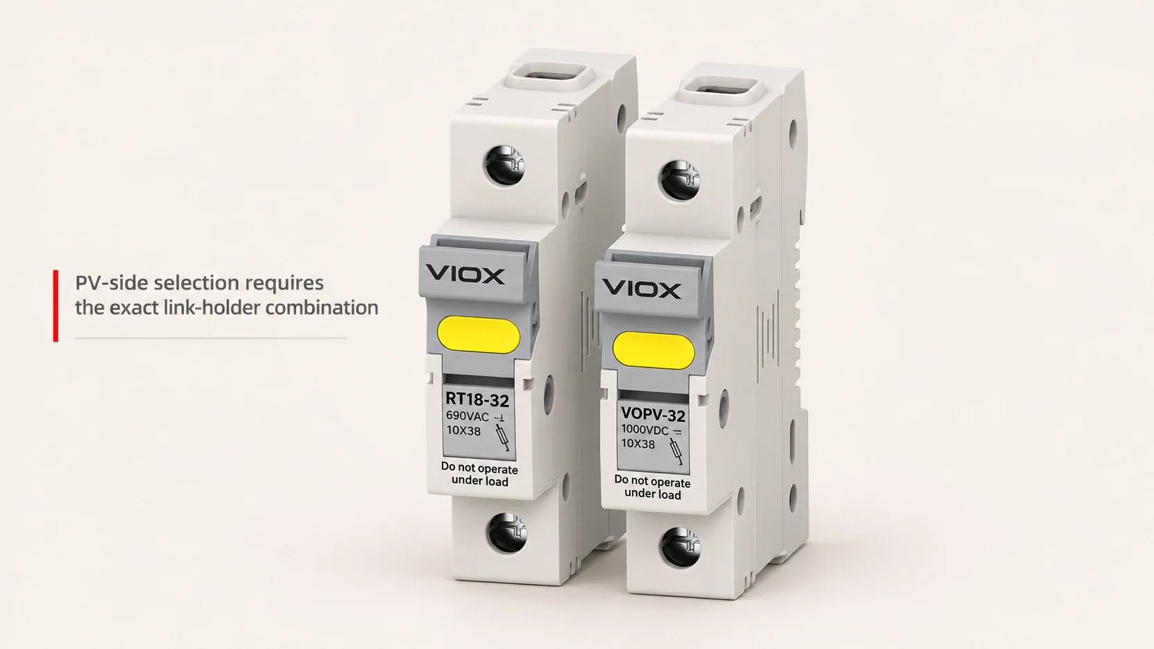
Do not use VOB6-63DC as the battery-circuit recommendation from this article. A general DC catalog description does not establish suitability for a particular battery, fault level or installation. Battery-side selection needs its own approved system documents; it cannot be inferred from the breaker name or ampere range. VIOX Solar does not offer a 1500 V combiner box.
Related resources
- DC Fuse Guide
- gPV vs gG Fuse
- What Is a PV Combiner Box?
- How to Select a PV Combiner Box
- PV DC SPD Voltage Selection
- What Is a DC Isolator Switch?
- Why Does a PV String Fuse Keep Blowing?
FAQ
Is home battery storage safe?
A properly specified, installed and maintained home battery system can be used safely, but no system is risk-free. Check the approved battery/inverter combination, BMS response, DC overcurrent protection, isolation, connections and placement. LFP generally has better thermal stability than NMC, but it still needs those safeguards and qualified installation.
Can a home battery catch fire?
Yes. Internal cell defects, damage, overcharge, excessive temperature or faults in the surrounding electrical system can lead to fire. An LFP battery system is not fireproof or immune to thermal runaway. Follow the manufacturer's instructions and recall notices, and have damage, unusual heat or repeated safety alarms assessed rather than resetting and continuing to use the system.
What causes most solar storage fires?
The reviewed evidence does not establish a universal majority cause for home solar-storage fires. Faulty connections and DC protection are important potential ignition paths, but battery control, assembly and cell faults also matter. Rooftop-PV connector statistics cannot be relabeled as battery-fire statistics. Check both the PV circuit and the battery circuit instead of assuming one is responsible for most incidents.
Do I need a fuse on my battery?
The battery circuit needs the overcurrent protection specified by the approved battery system and local rules. It may use an integrated protective device, an external fuse/breaker or a documented combination. Ask for its location, DC voltage/current duty, interruption capability and cable-protection basis. A BMS or PV string fuse alone does not automatically establish adequate battery-circuit protection.
Is DIY lithium battery storage safe?
An improvised home-storage pack made from unmatched or untraceable cells cannot be treated as equivalent to a documented complete system. Safe assembly requires verified cells, mechanical and thermal design, BMS control, fault protection and a suitable inverter/charger combination. For a home installation, use a system with the applicable approval evidence and a qualified installer; do not assume that adding a BMS makes a DIY pack safe.