
A PV string fuse that keeps blowing may be responding to a circuit fault, an unsuitable fuse or holder combination, abnormal heating, or another condition that needs investigation. An open fuse confirms an interruption at that point; it does not identify the cause. Record the event and establish the evidence before replacing the link or changing its rating.
This checklist is for PV operations teams, qualified service personnel and engineers investigating a string circuit. It helps organize a fault investigation and its handoff. It does not authorize live testing or replace the site's electrical safety procedure, equipment instructions or project-specific protection design.
Establish a safe investigation boundary
PV modules can produce voltage when illuminated. Parallel strings, inverters, batteries or other connected equipment may provide additional energy paths. A zero-current reading, an inverter shutdown or an open fuse does not by itself establish that the relevant conductors are safe to touch.
Qualified, authorized personnel should identify the sources and work boundary, follow the site-specific energy-control procedure and equipment instructions, and verify the isolation state using the required method and appropriately rated equipment. The U.S. OSHA solar lockout/tagout guidance explains source identification, isolation and verification in its U.S. safety context; apply the requirements adopted at the actual site.
Do not open a fuse carrier under load. The VIOX RT18-32 / VOPV-32 product page expressly prohibits load operation of its carrier. Do not bypass a fuse or repeatedly install replacement links to reproduce the failure. Smoke, arcing, melted parts, water in electrical equipment or an unknown isolation state are reasons to stop work and follow the site's escalation procedure.
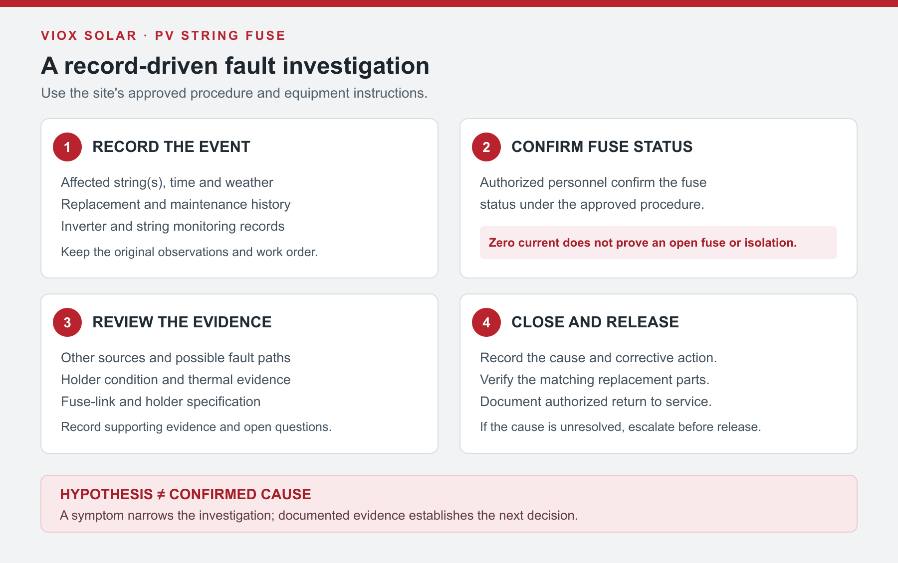
Record the event before the evidence is lost
One complete incident record is more useful than a list of possible causes. Capture what is already available from monitoring and maintenance records before a failed link or damaged holder is discarded.
| Record field | What to capture |
|---|---|
| Location and boundary | Site, combiner, input position, affected string, inverter/MPPT group and drawing revision |
| What actually happened | Alarm text, zero or low current, confirmed open link, visible damage, or another observation; identify how each was established |
| Timing and conditions | Time, irradiance or weather records if available, operating state, and whether the event followed rain, maintenance or a configuration change |
| Scope and history | Same string or multiple inputs, number and dates of previous events, replaced parts and any unresolved prior work |
| Protection details | Fuse-link and holder markings or part numbers, PV/DC voltage and current ratings, utilization category, physical format and approved specification |
| Evidence still needed | Diagrams, module datasheet, monitoring history, authorized inspection or test results, owner and due date |
Mark unknown fields as unknown. Do not record a suspected short circuit as a confirmed cause until the investigation supports it. For the broader enclosure and commissioning context, see the PV combiner box installation and troubleshooting checklist.
Confirm what failed: monitoring, fuse link or holder
An inverter channel showing zero string current does not prove that a fuse has opened. An open connector, conductor, monitoring channel or equipment operating state may also explain missing current. Compare the record with the actual circuit layout and comparable operating conditions; similar-looking channels may serve different MPPT groups or orientations.
After the equipment has been placed in the required safe state, a qualified person can confirm the link's condition using the approved equipment procedure and suitable instruments. A verified open link answers whether the link is open, not why it opened. A damaged or discolored holder is a separate finding: the holder may have heat damage even if the link has continuity, and an open link may show no visible external damage.
Do not use a current reading as proof of isolation. Fluke's discussion of non-load-break PV disconnects notes that an incorrectly applied clamp measurement can read zero even when current is present. Voltage and all energy sources remain subject to the site's prescribed verification procedure.
Turn each observation into a testable question
Use the table to decide what information is missing. A single symptom can fit several explanations; the next action is to obtain evidence under an approved procedure, not to treat the first plausible cause as proven.
| Observation | Hypothesis to investigate | What it does not prove | Evidence to request or review |
|---|---|---|---|
| The same string has two confirmed open links | A string-specific fault, intermittent condition, or protection mismatch | That a short circuit or reverse current caused both events | Circuit history, string diagram, authorized inspection/test results and exact link records |
| Several inputs report events around the same period | A shared environmental, configuration, source or monitoring issue | That all links physically opened or share one cause | Event timestamps, channel mapping, holder conditions, environmental records and confirmed link states |
| A holder or termination is discolored | Local heating or damage at the contact or termination | That the link opened, or that its current rating is adequate | Safely obtained inspection records, exact holder/link compatibility and relevant temperature and load history |
| Events follow rain or high humidity | An intermittent moisture-related insulation or entry problem | That a ground fault caused the fuse operation | Weather and alarm history; authorized inspection and project-approved diagnostic results |
| The installed link differs from the approved schedule | A replacement or specification mismatch | That the deviation alone caused the event | Link part number, PV duty, time-current data, voltage, breaking capability, holder and approved design record |
The evidence may support more than one path at once. If the facts conflict, keep the cause open and assign the next verification to the responsible engineer or service team.
Investigate the three main evidence paths
1. Circuit fault and available source paths
Review the as-built diagram, affected string and events surrounding any changes. A faulted string may receive current from other parallel strings or another connected source, depending on the actual architecture. Identify those paths and the protection boundary before interpreting the event. Reverse current is a possible mechanism; an open fuse alone does not establish that it occurred.
Authorized personnel should use the equipment manufacturer's and site's approved inspection and diagnostic procedures to investigate conductors, connectors, modules, insulation and other relevant equipment. An insulation or ground-fault alarm deserves investigation, but it does not establish that the same event opened the fuse. Document the relationship or leave it unresolved.
2. Holder, terminations and enclosure heat
Contact condition, conductor termination, mounting, neighboring devices and enclosure temperature can affect the fuse assembly. Compare available temperature records only under meaningful operating conditions and within equipment instructions. A hot location can identify an area for inspection; it does not by itself prove a failed contact or the cause of a link opening.
For example, Fluke's thermal-imaging guidance for electrical systems describes comparing similar components and investigating anomalies. A fuse that has already opened may no longer carry load, so an image taken afterward may not reproduce the earlier heating. Record when an image was taken, what was energized, and whether comparison points had comparable loading. Do not use a universal temperature difference as a pass/fail limit.
After safe isolation, inspect the holder and terminals under the prescribed procedure. A melted, cracked, arced or otherwise damaged part needs assessment and appropriate replacement under the manufacturer's instructions; merely cleaning or tightening it does not establish that damaged insulation or contacts are serviceable.
3. Fuse-link and protection specification
Compare the installed link and holder with the approved parts and the current circuit design. Check the exact link's PV/DC duty, voltage, current rating, breaking capability, time-current behavior and physical compatibility, as well as the holder and installed temperature conditions. Review module and conductor protection limits and any changes to the array since the original design.
The VIOX DC fuse guide explains how these ratings fit together. Matching the old link's ampere marking is useful identification, but the same ampere value alone does not establish an equivalent replacement. A larger fuse is a proposed design change—not a diagnostic fix—and requires a fresh protection review.
For the product referenced here, the public page identifies VOPV-32 as the photovoltaic DC version, with a 10 × 38 mm format and a listed 1000 V DC rating; RT18-32 is the AC version. Confirm the exact fuse-link and holder part numbers and controlled documentation for the installed configuration. The shared format or family page does not prove that an AC version, arbitrary fuse-link or another current option is suitable for the PV circuit.
Two hypothetical investigation records
These examples show how the same checklist can lead to different next actions. They are invented teaching scenarios, not VIOX customer cases or measured field results.
Scenario A: The same input opens after rain
The maintenance record says input S3 had a confirmed open link on two occasions, each after rain. Other monitored inputs reported normal operation, and no holder condition has yet been documented.
- Known: two open-link confirmations and weather timing appear in the record.
- Hypotheses: an intermittent string/insulation condition, moisture at an entry or connector, or another string-specific issue. A specification mismatch could still be present.
- Not established: the physical fault location, whether moisture caused either opening, or whether reverse current operated the link.
- Next evidence: the approved S3 source diagram, exact replacement history, site weather/alarm records and authorized inspection/diagnostic findings. The service engineer records which findings support or rule out each hypothesis.
Suppose an authorized test, conducted under the approved equipment procedure, finds S3 insulation below the applicable project or manufacturer acceptance limit. That finding supports an insulation investigation and further localization; it does not by itself prove how or why the fuse opened. A result within the limit also does not rule out a defect that appears only intermittently.
The rain correlation sets an investigation priority. It does not authorize replacing the fuse with a larger one or declare a ground fault as the cause.
Scenario B: A discolored holder, but the link shows continuity
In a separate hypothetical inspection, a qualified technician records discoloration at one holder after the equipment is placed in the required safe state. The removed link is verified as continuous under the approved procedure. No pre-event thermal image or load history is available.
- Known: holder discoloration and a continuous link at the time of the approved check.
- Hypotheses: contact or termination heating, prior damage, or environmental stress requiring further investigation.
- Not established: that a link opened, how hot the connection became, or whether the installed link was suitable for the project.
- Next evidence: holder and terminal condition, exact replacement compatibility, installation records and the manufacturer's disposition of the damaged assembly. Review historical loading if available; do not invent a temperature value.
This is a holder-condition investigation. It should not be recorded as a confirmed blown-fuse event merely because the enclosure shows heat damage. Continuity alone does not prove that the link can safely operate at its rated voltage and current or that it is suitable for reuse.
Close the investigation before return to service
Use the project work order to record the following:
- The confirmed event and affected circuit, with evidence references and any unknowns.
- The cause supported by the investigation, or the reason it remains unresolved and the escalation owner.
- The repair or design correction, including the disposition of any damaged holder, terminal, conductor or enclosure part.
- The approved replacement link and holder identities, and their compatibility with the documented circuit and installed conditions.
- Required inspection and test records, drawing or maintenance updates, and the authorized person's release decision under the site's procedure.
If the cause or protection configuration cannot be established, keep the circuit in the state required by the site procedure and escalate. A successful restart alone does not demonstrate that the original problem or protection coordination has been resolved.
For a VOPV-32 replacement or component review, send the affected circuit diagram, existing link and holder markings, event record, environmental conditions and target-market requirements to sales@vioxsolar.com. Request controlled documents for the exact parts; final fault diagnosis and release remain with the responsible site team.