
For PV DC SPD voltage selection, start with the string's maximum open-circuit voltage under the project's design conditions, including the required cold-weather correction. Check that the SPD's documented Ucpv covers that requirement for the specified protection modes. Then verify its voltage protection level, Up, against the protected equipment and installation design.
A continuous-voltage comparison is one selection step. The final decision also depends on the SPD circuit, earthing arrangement, surge duty and model documentation. This guide uses IEC terminology for PV array circuits; the applicable local rules and current module instructions establish the project calculation basis.
Keep string Voc, Ucpv and Up separate
These values answer different engineering questions:
| Quantity | What it describes | Selection use |
|---|---|---|
| Module Voc at STC | One module's open-circuit voltage at standard test conditions | Starting input for the string calculation |
| Maximum string Voc, or Uoc,max | The highest design open-circuit voltage for the string | Voltage requirement derived from the approved method and conditions |
| SPD Ucpv | Permitted continuous PV DC voltage for a specified protection mode | Check continuous-voltage suitability |
| SPD Up | Declared voltage protection level under the relevant surge test conditions | Coordinate surge limitation with equipment withstand and the installation |
The public IEC 61643-32 preview, definition 3.18, relates Ucpv to the SPD's protection mode and to maximum open-circuit voltage. The basic comparison is:
Ucpv ≥ Uoc,max
Apply it with the correct circuit arrangement and any additional requirements in the governing selection method. Ucpv and Up are separate ratings: an SPD labeled for 800 V continuous operation can have a protection level expressed in several kilovolts.
Use Voc for this check. Module power, operating voltage Vmp and the inverter's MPPT operating range do not establish maximum string open-circuit voltage.
Collect the inputs before choosing an SPD voltage
Record these items for each electrically distinct string or array section:
| Input | Required detail |
|---|---|
| Module identity | Exact model, datasheet revision and installation instructions |
| Module Voc | STC value and any applicable voltage tolerance |
| Voc temperature coefficient | Value, sign and units: %/°C or V/°C |
| Series count | Modules in the string being evaluated |
| Minimum design temperature | Value and source required by the approved calculation method |
| Other design allowances | Required tolerances, environmental effects or prescribed factors |
| Circuit arrangement | Earthing, inverter topology and required SPD protection modes |
| Equipment limits | Maximum DC voltage and separately documented impulse withstand |
Use the project's required minimum temperature rather than a seasonal average or the temperature observed during installation. Where the module instructions specify minimum ambient temperature, use that basis. A method requiring an estimated minimum cell temperature must use that different basis consistently.
Parallel strings increase available current; do not multiply string voltage by the number of parallel strings. Their current contribution remains relevant to the SPD's short-circuit suitability and disconnection arrangement in the wider solar DC protection selection workflow.
Calculate cold-weather string Voc with the correct coefficient
Where the module instructions and project rules permit a linear temperature-coefficient method, the calculation can be written as:
Uoc,cold = N × Voc,STC × [1 + betaVoc × (Tmin − 25°C)]
Here, N is the series module count and betaVoc is the signed fractional coefficient per °C. For example:
−0.25%/°C ÷ 100 = −0.0025/°C
For a negative coefficient, cooling below 25°C produces a positive voltage increase. Keep the coefficient's negative sign when using the formula above.
The Trina Solar Vertex installation manual, section 6.4.1, illustrates this form using minimum ambient temperature. Use it as a method reference; the current instructions for the actual module and the destination's design requirements control the project calculation.
If the datasheet instead gives a coefficient in V/°C, the module correction is additive: Voc,STC + coefficient × temperature difference. Do not insert that absolute coefficient into the fractional formula.
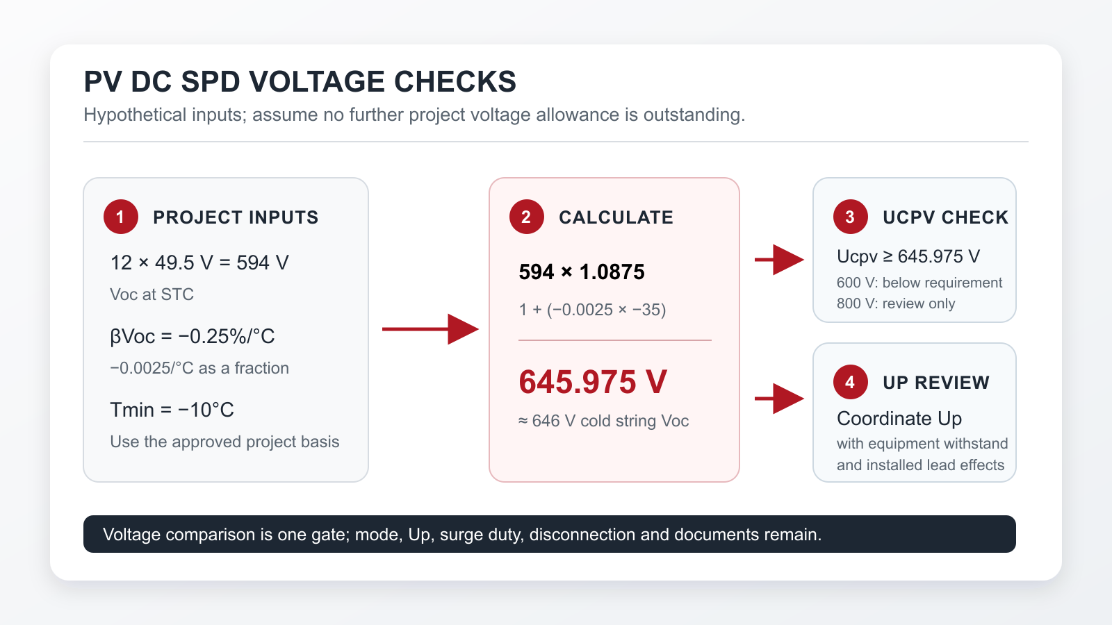
Worked example: 594 V at STC becomes approximately 646 V
Assume a hypothetical project has these approved inputs:
- 12 identical modules in series.
- Module Voc at STC: 49.5 V.
- Voc temperature coefficient: −0.25%/°C.
- Minimum temperature used by the approved method: −10°C.
For this example, assume the stated method and inputs already satisfy the project voltage basis, with no further allowance outstanding. These are teaching values, not the specifications of a named module or an actual installation.
| Calculation | Result |
|---|---|
| String Voc at STC: 12 × 49.5 V | 594 V |
| Temperature difference: −10 − 25 | −35°C |
| Correction factor: 1 + (−0.0025 × −35) | 1.0875 |
| Cold-weather string Voc: 594 × 1.0875 | 645.975 V |
The result is approximately 646 V. A 600 V candidate is below the calculated requirement even though 594 V appeared to fit at STC. Retain the unrounded result when comparing a candidate near its limit.
In a real design, reconcile this result with every required tolerance and environmental allowance before calling it the final Uoc,max. A fixed multiplier found in another guide may belong to a different method or starting voltage. Identify its scope before applying it; do not substitute an unexplained multiplier for the documented project calculation.
Compare the VO-PV40 references as initial candidates
The VO-PV40 product page lists these continuous-voltage references and corresponding Up values:
| Public continuous-voltage reference, labeled Ucp | Listed Up |
|---|---|
| 500 V DC | 2.8 kV |
| 600 V DC | 3.2 kV |
| 800 V DC | 3.5 kV |
| 1000 V DC | 3.8 kV |
| 1200 V DC | 4.5 kV |
| 1500 V DC | 5 kV |
These are public catalog values for initial comparison. Obtain the controlled datasheet confirming Ucpv for the selected protection modes, the exact order reference and the relevant Up test basis before approving a configuration.
For the hypothetical 645.975 V requirement:
- 600 V: below the requirement; exclude it on this voltage comparison.
- 800 V: above the requirement; retain it for documentation and coordination review.
- 1000 V: also above the requirement; evaluate its listed 3.8 kV Up alongside the 800 V reference's listed 3.5 kV Up.
The highest voltage reference is not automatically the best protective choice. This catalog's higher-voltage options also have higher listed Up. Select a candidate that meets both the continuous-voltage requirement and the project's surge-protection objective.
The VIOX PV DC SPD family page provides the commercial range. The calculation above does not constitute approval of a particular VO-PV40 order code.
Confirm the protection mode before accepting the voltage match
The voltage applied to an SPD depends on how its protective elements are connected. Request the manufacturer's circuit and mode table for the actual earthing and inverter arrangement.
The VO-PV40 page lists DC+ to PE and DC− to PE protection, alongside two-module and three-module options. Confirm which configuration provides each required mode and its associated Ucpv and Up. If the design requires protection between DC+ and DC−, obtain the documented performance of that path as well.
For an unearthed array, do not assume that each pole remains at half the string voltage relative to earth. Potential shifts and relevant fault conditions must be addressed by the approved SPD arrangement. Likewise, adding cartridge voltage labels together does not establish a complete multipole device rating.
IEC 61643-31 covers requirements and testing for PV DC SPDs within its scope; IEC 61643-32 addresses selection and application. Request PV-duty evidence and the locally applicable documents for the exact reference. A voltage label or generic SPD standard reference alone leaves that evidence incomplete.
Check Up against equipment withstand and the installed arrangement
After continuous voltage and protection modes are established, obtain the protected equipment's impulse withstand data and the project's permissible protection level, including its required coordination margin.
The inverter's maximum continuous DC input voltage and its impulse withstand describe different stresses. A 1000 V input rating, for example, supplies no stand-alone answer about the permissible surge protection level.
Review:
- The SPD's Up for the relevant mode and declared test conditions.
- The protected equipment's applicable impulse withstand.
- Additional voltage along the SPD connection conductors.
- Cable routing, distance to the equipment and coordination with other SPDs.
The Phoenix Contact surge-protection handbook explains how inductive voltage along connecting conductors can reduce the installed protective effect. That principle is why a catalog Up comparison alone cannot establish the voltage reaching the equipment. Use the applicable PV design rules and device instructions for the actual arrangement.
For VO-PV40, a listed Up of 3.5 kV is therefore an input to coordination, rather than a guarantee of a 3.5 kV limit at remote equipment. If the project's permitted protection level or mode-specific data is missing, record the candidate as awaiting verification.
For a numerical illustration, assume a project's coordination study permits a catalog Up no greater than 3.6 kV for the specified mode and test basis, after accounting for its required margin and installation effects. A verified 3.5 kV candidate meets that particular criterion; a 3.8 kV candidate exceeds it. The 3.6 kV limit is a hypothetical project input, not an inverter specification or a default rule. Matching VIOX values to it still requires the controlled mode and test data.
Complete a voltage-selection record before ordering
Use this worksheet to turn the calculation into a traceable specification:
| Record field | What to enter or attach |
|---|---|
| Circuit identity | String/array section, MPPT assignment and approved drawing revision |
| Source data | Module model, Voc, coefficient units/sign, tolerance and series count |
| Temperature basis | Minimum design temperature, its source and the calculation method |
| Final voltage requirement | Unrounded Uoc,max with all applicable allowances resolved |
| Candidate identity | Exact SPD voltage reference, module arrangement and order code |
| Mode confirmation | Manufacturer's circuit, required modes and documented Ucpv by mode |
| Protection coordination | Up basis, equipment impulse withstand, margin, routing and location |
| Remaining SPD requirements | Type/surge duty, short-circuit rating, disconnection and backup protection |
| Decision | Excluded, awaiting verification, or accepted within the approved design |
Send the completed inputs to sales@vioxsolar.com when requesting a VO-PV40 review. Ask for the controlled voltage/mode table, installation instructions and documents matched to the destination market and quoted reference.
Where the SPD will be incorporated into a combiner, carry the approved requirements into the complete assembly specification using the PV combiner box selection checklist. The finished record should show why the candidate meets the voltage requirements and which documents support that decision.